Wisdom in mind, enthusiasm at heart.
|
|
Wisdom in mind, enthusiasm at heart. |
||||||
|
|
|
|
|
|
|
|
|
|
|
|
|
||
|
USB power supply setting : (Users can place the kit at outside as an USB to I2S/coaxial converter. If place in the gear but the gear have not enough power supply , users also can use USB power supply . ) 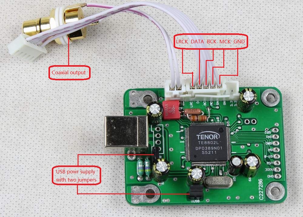
|
External power supply
setting: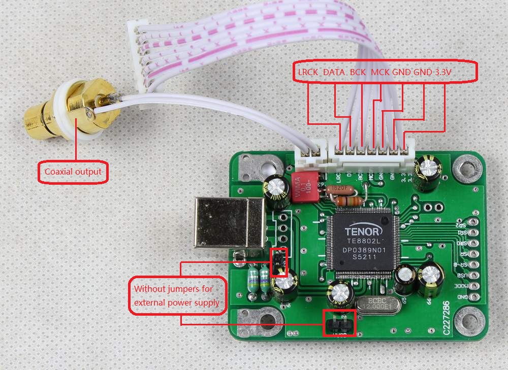 |
Best performance modify
advice: (Users can setting the TE8802 kit on external power supply model, connect a class A PSU module PSU-A for the power supply , boost the sound level to highest performance. In this model the TE8802 still have power from USB through the PSU-A .) 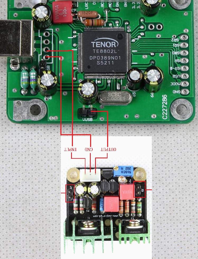 PSU-A link: (If order for TE8802, must inform while place the order) http://www.audio-gd.com/Pro/diy/PSU-M/PSU-AEN.htm |
|
Design: |
||
|
|
|
|
 |
|
|
|
|
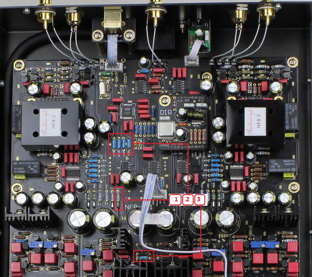
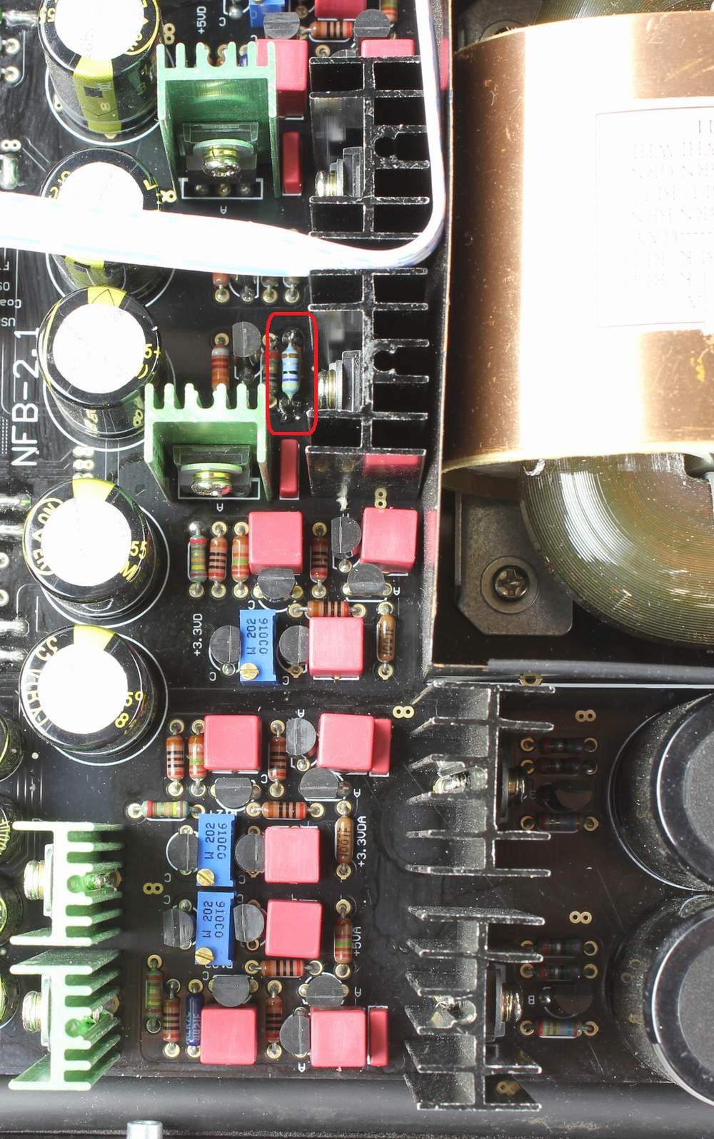
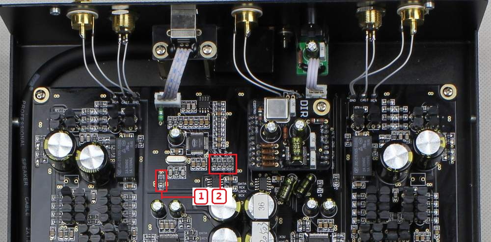
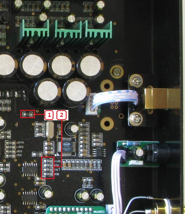
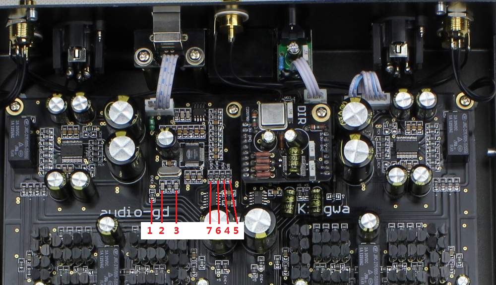
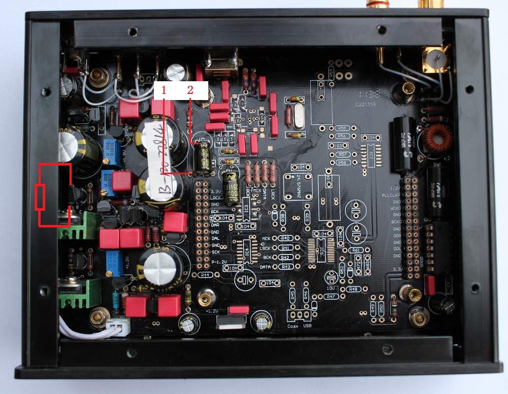
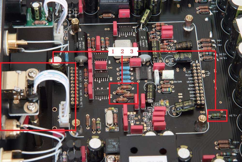
Step 1: Cut the extra parts on the
board . A , Cut the 5 resistors as the No.1 and No.2 in the photo on right side . B , Addition a resistor (4.7 ohm) on the either resistor in the No.3 . C , The wires number have mark on the TE8802 kit photo. |
|
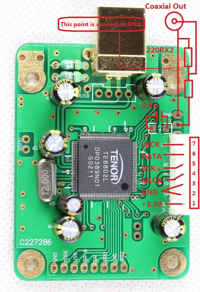
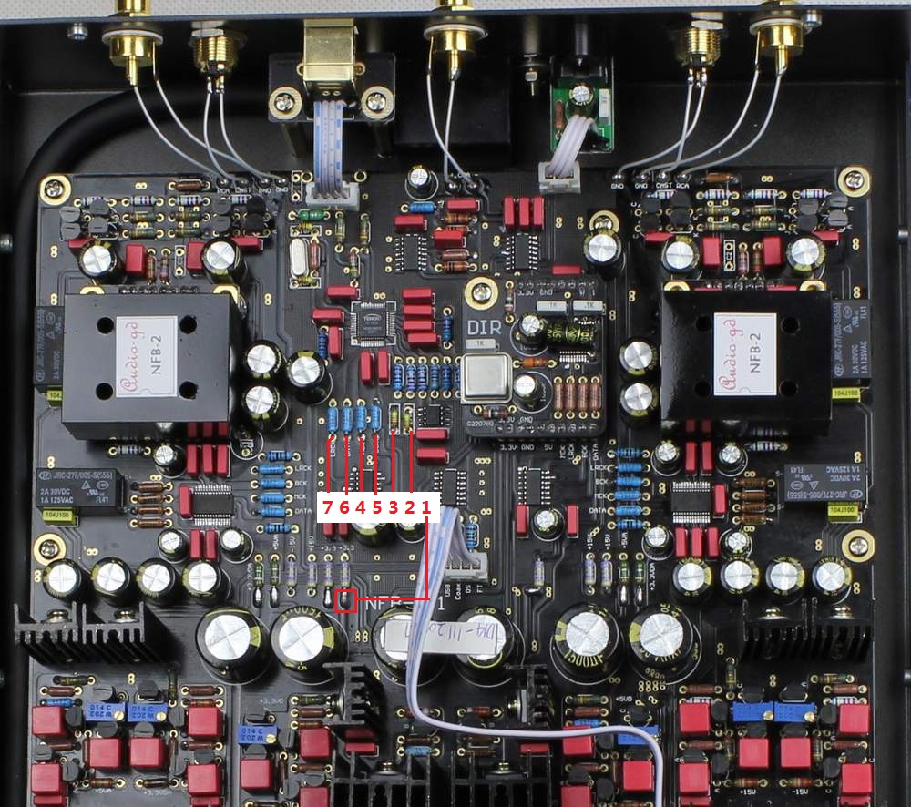
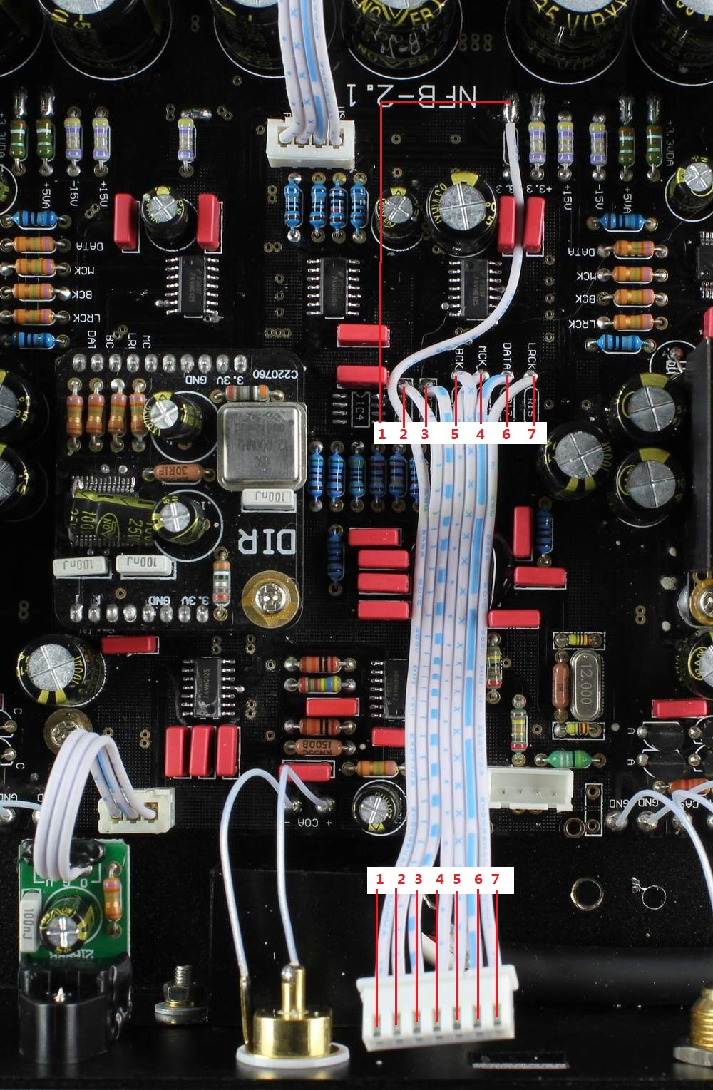
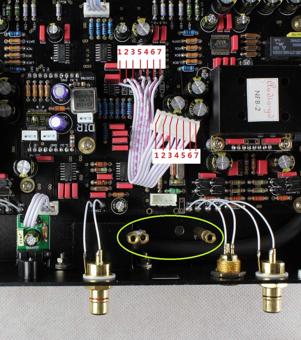
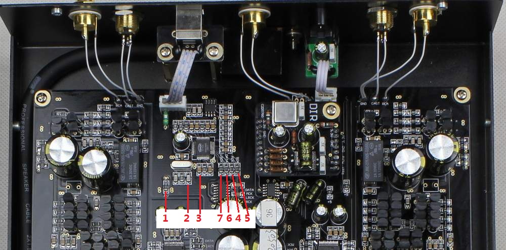
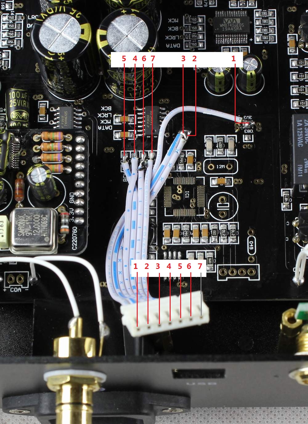
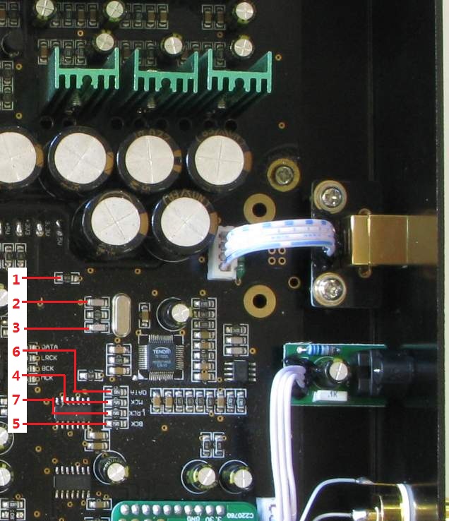
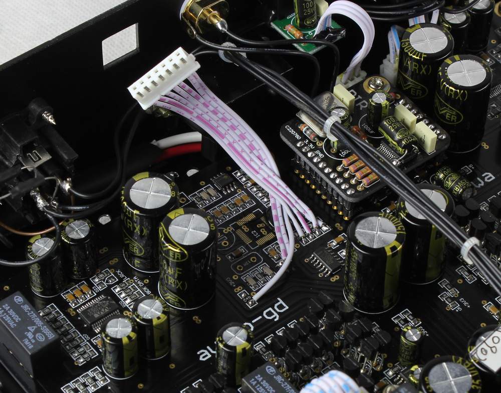
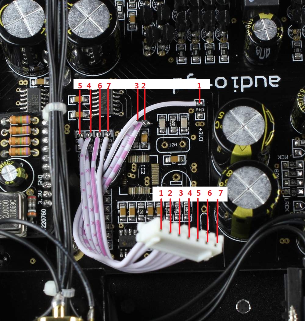
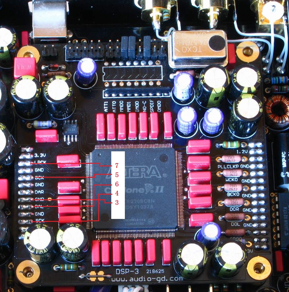
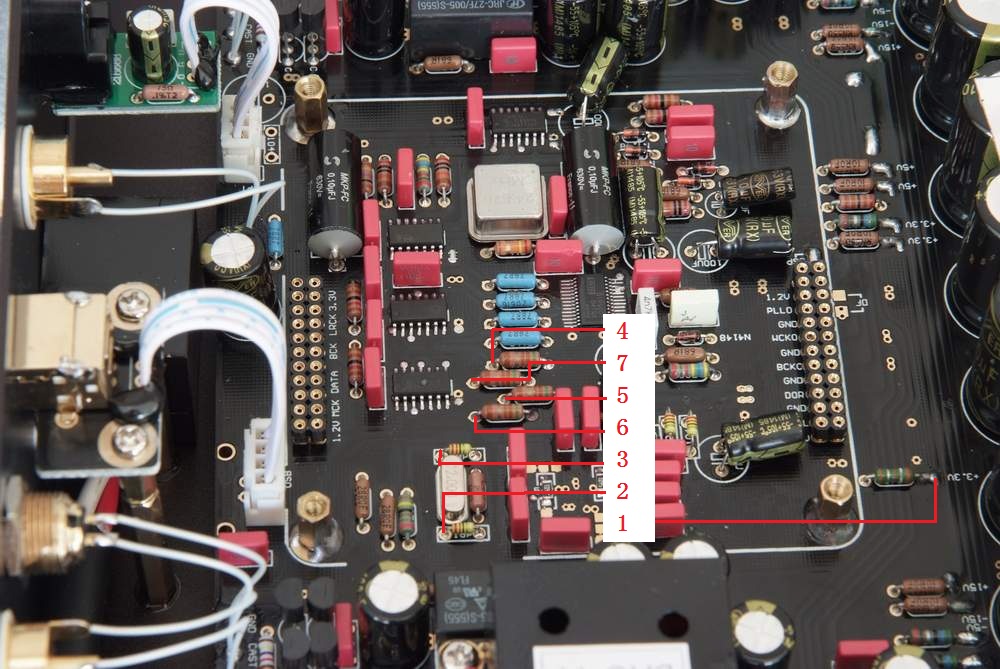
| Step 2: Connect the wires . The wires number had mark on the photos , must connect correct . |
 |
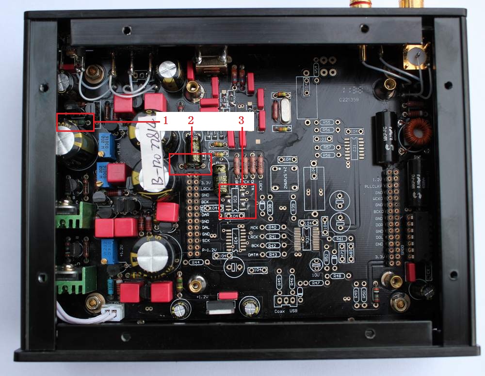
| Step 3 : Solder a resistor ( 4.7 ohm) as the photo . The NFB2, NFB2.1 have class A PSU, this resistor is for boost the current of the PSU . If users install I2S instead TE8802 kit, this resistor must take off . |
 |
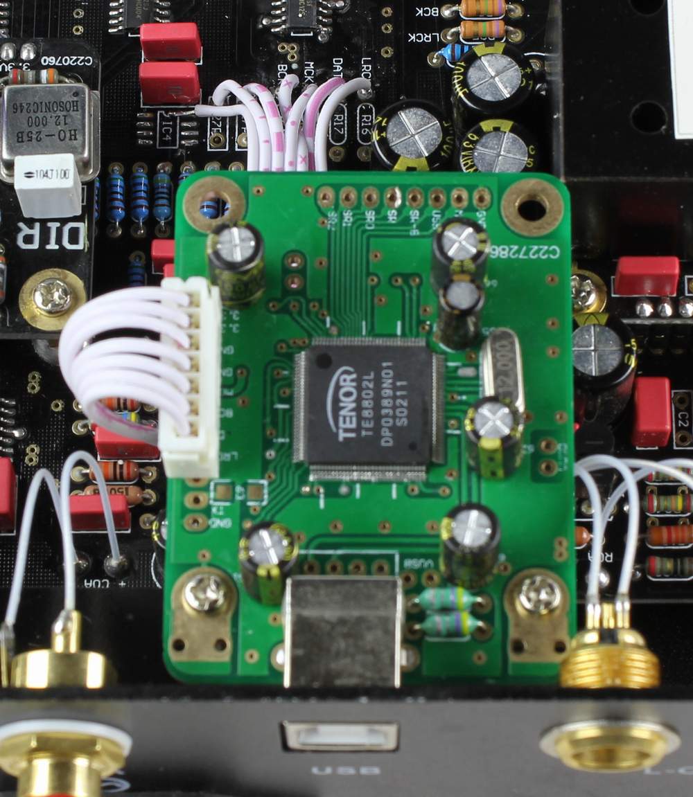
| Step 4 : Take off the original USB socket board and struts . Install the new two struts on here . The struts is made by handwork, so even we are try our best but maybe have little error . I beg you understanding . |
 |
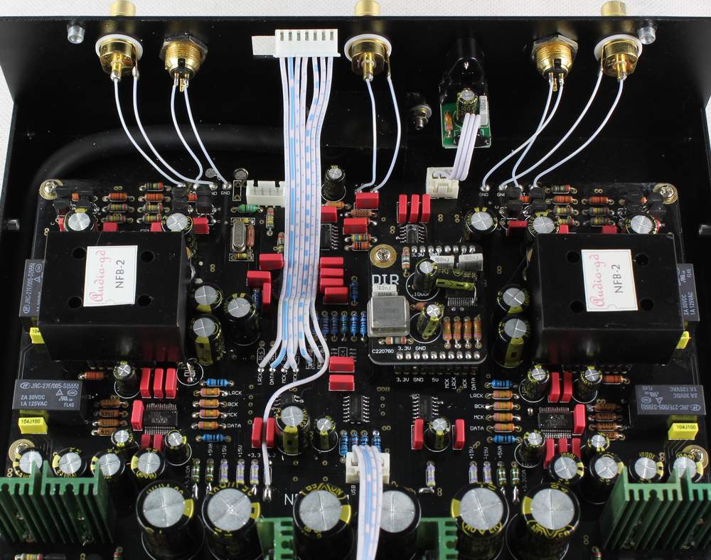
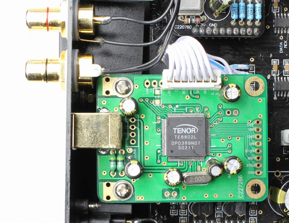
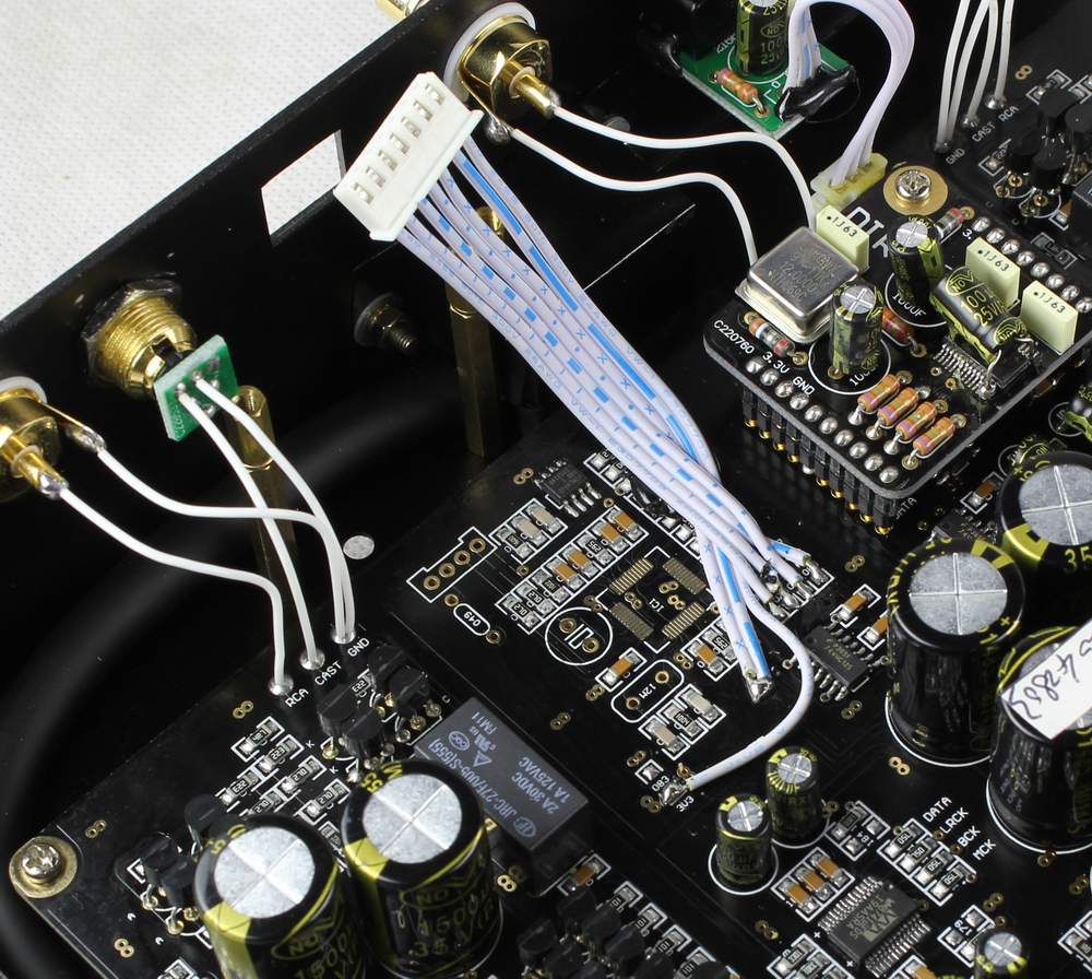
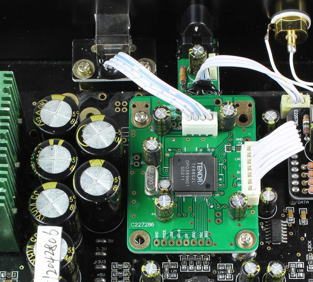
| Step 5 : Install the kit . Push into the wires on the kit and finished . If the wires have not any wrong connect, you can connect the PC and enjoy the music at next steps . |
 |
|
|
|
|
Step 1: Cut the extra parts on the
board . A , Cut the 5 resistors as the No.1 and No.2 in the photo on right side . B , The wires number have mark on the TE8802 kit photo. |
|
| Step 2: Connect the wires . The wires number had mark on the photos , must connect correct . |
 |
| Step 3 : Take off the original USB socket board and struts . Install the new two struts on here . The struts is made by handwork, so even we are try our best but maybe have little error . I beg you understanding . |
|
| Step 4 : Install the kit . Push into the wires on the kit and finished . If the wires have not any wrong connect, you can connect the PC and enjoy the music at next steps . |
|
|
|
|
|
Step 1: Cut the extra parts on the
board . A , Cut the 5 resistors as the No.1 and No.2 in the photo on right side . B , The wires number have mark on the TE8802 kit photo. |
|
| Step 2: Connect the wires . The wires number had mark on the photos , must connect correct . |
 |
|
Step 3 : Solder two struts on proper area , ( you
want to scrape some black paint for solder the struts ) Install the kit . Push into the wires on the kit and finished . If the wires have not any wrong connect, you can connect the PC and enjoy the music at next steps |
|
|
|
|
|
Step 1: Cut the extra parts on the
board . A , Cut the 5 resistors as the No.1 and No.2 in the photo on right side . B , The wires number have mark on the TE8802 kit photo. |
|
| Step 2: Connect the wires . The wires number had mark on the photos , must connect correct . |
 |
| Step 3 : Take off the original USB socket board and struts . Install the new two struts on here . The struts is made by handwork, so even we are try our best but maybe have little error . I beg you understanding . |
|
| Step 4 : Install the kit . Push into the wires on the kit and finished . If the wires have not any wrong connect, you can connect the PC and enjoy the music at next steps . |
|
|
|
| Simply pull off the original USB module and push into the TE8802 kit . Before power on it, users want to screw on the screws for confirm the install is correct . |
|
|
|
|
Step 1: Cut the extra parts on the
board . A , Cut the 2 resistors as the No.1 and No.2 in the photo on right side . B , Remove the tins in No.3 as the photo. |
 |
|
Step 2: A, Addition a 5.6 ohm in the DI as the photo . B ,Connect the wires . The wires number had mark on the photos , must connect correct . |
|
|
|
|
|
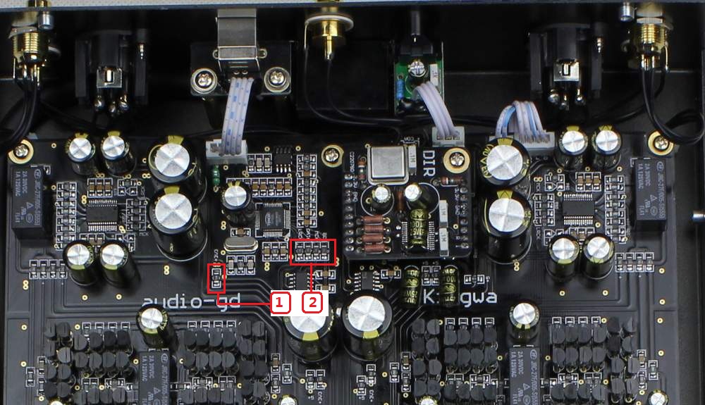
Step 1: Cut the extra parts on the
board . A , Take off the DSP-1 careful, don't break the pins . B , Take off the USB socket as the No.1 in the photo. C , Cut the 5 resistors as the No.2 and No.3 in the photo on right side . |
 |
| Step 2: Connect the wires . The wires number had mark on the photos , must connect correct . Install the DSP-1 correct . |
|
| Step 3 : Install the new two struts and the TE8802 kit . The struts is made by handwork, so even we are try our best but maybe have little error . I beg you understanding . | |
|
备案序号:粤ICP备05020367号 版权所有: 何庆华 睿志音响 Copyright(C) 2004 www.audio-gd.com All Rights Reserved |