|
Performance improve advice:
A,If you had some skill on DIY and had the ES9018 built in DAC.
You can try the below advice.
Both RJ45 and HDMI I2S transmit models, the most ES9018 had not
request the MCLK signal, you can cut the MCLK wire in the source ,
connect to GND or chassis if it is connect to GND.
Please Note:
1,After this modify, the I2S source only can working with ES9018
built in DACs and the design don't request on the MCLK.
2,The DIY always had the risk , we can't warranty any people can
finished the modify succeed and safe on the unit.
B, For compatibility with other brands,the default data line up is : DATA, BCLK, WCK, MCLK, GND.
You can try the new line up but it is may not compatibility with
other brands :
DATA, WCK, BCLK, MCLK, GND .
You just want to exchange the WCK and BCLK wires in the input module
output side and the output module input side. |
 |
|
HDMI model pins define:
Pin 1 : SDATA -
Pin 2 : GND
Pin 3 : SDATA +
Pin 4 : SCLK +
Pin 5 : GND
Pin 6 : SCLK -
Pin 7 : LRCK -
Pin 8 : GND
Pin 9 : LRCK +
Pin 10: MCLK +
Pin 11: GND
Pin 12: MCLK -
Pin 13: NC
Pin 14: NC
Pin 15: NC
Pin 16: NC
Pin 17: GND
Pin 18: NC
Pin 19: Auto on control (Available in the input kit .Non use in the
output kit, but can custom order.)
The Pins define of the SDATA,SCLK, LRCK and MCLK can be exchange by
users.
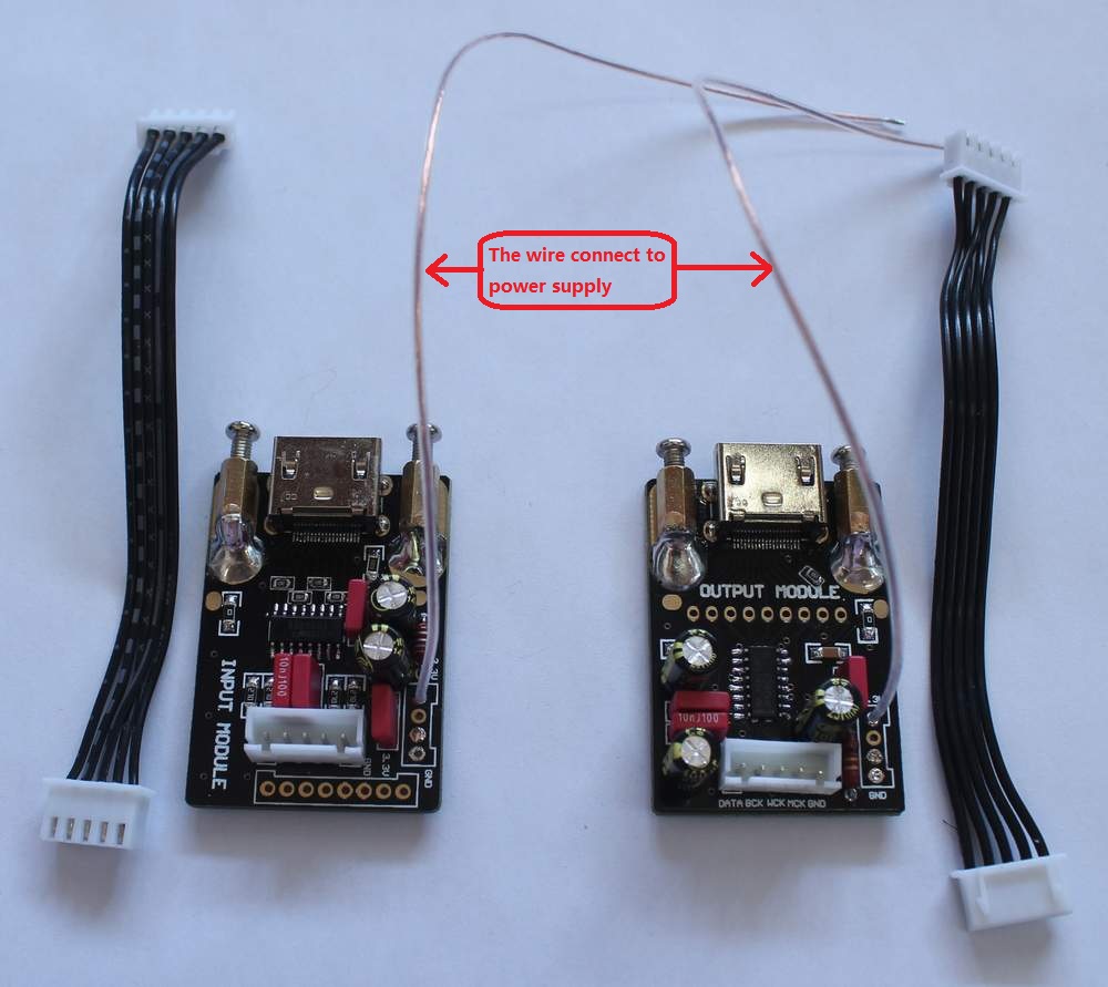
The I2S output kit can power supply by +3.3V (max 3.5V). Power spend
around 25MA . The output kit had setting always ON .
The I2S input kit must power supply by +3.3V (max 3.5V), power spend around
15MA.
The one wire on the kit connect to the power supply, the 5 wires
connect to GND ,SDATA ,SCLK, LRCK and MCLK .
The kits up to 32 bit 384KHz support but depend on the HDMI cable
quality , the HDMI cable shorter is better .
Please note: Don't hot push / pull of
the I2S cable. Any time must power off the units then push or pull
the I2S cable.
The kit had full test before shipping, we don't offer the warranty
because it can easy shatter by users wrong operate .
If customer want to replace the USB32 in audio-gd's DAC, please
inform while place the order. |
|
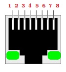
RJ45 model pins define:
Pin 1 : SDATA
Pin 3 : LRCK
Pin 5 : SCLK
Pin 7 : MCLK
Pin 2,4,6,8 GND
The Pin 1, Pin 3, Pin 5,Pin 7 can be exchange the define by users.
The kits up to 32 bit 384KHz support but depend on the CAT5 cable
quality, the CAT5 cable shorter is better . |
 |
HDMI model input kit modify guide
(The DIY always had the risk , we can't warranty any people can
finished the modify succeed and safe on the unit.) |
|
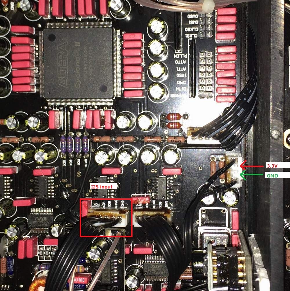
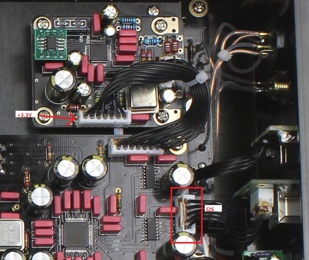
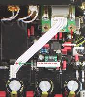
For Master 7:
( please inform for Master 7 modify while place the order, no solder
necessary .)
1, Pull off the original I2S kit and its wires.
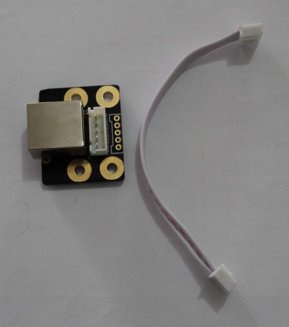
2, Assemble the HDMI input kit and push into the wires to the
I2S input on board socket.
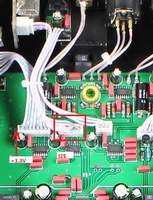
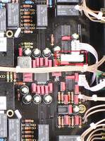
3, Push into the +3.3V wire in the +3.3V socket, see the photo on
right. |
 |
|
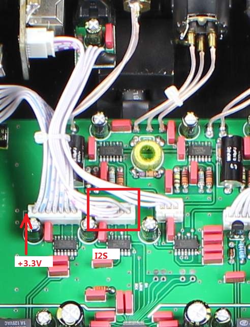
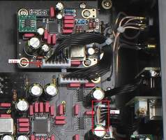
For the NFB-1(2015)
and NFB-29:
( Order the Type 1 input kit, if you can't solder, please inform
”For NFB-1(2015) avoid soldering"
while place the order . We will build the +3.3V wire with the USB
connect wires, customer want to replace the USB connect wires for
avoid solder .)
1, Pull off the original I2S kit and its wires.
2, Assemble the HDMI input kit and push into the wires to the
I2S input on board socket.
3, Soldering the +3.3V wire in the +3.3V point, see the photo on
right. |
 |
|
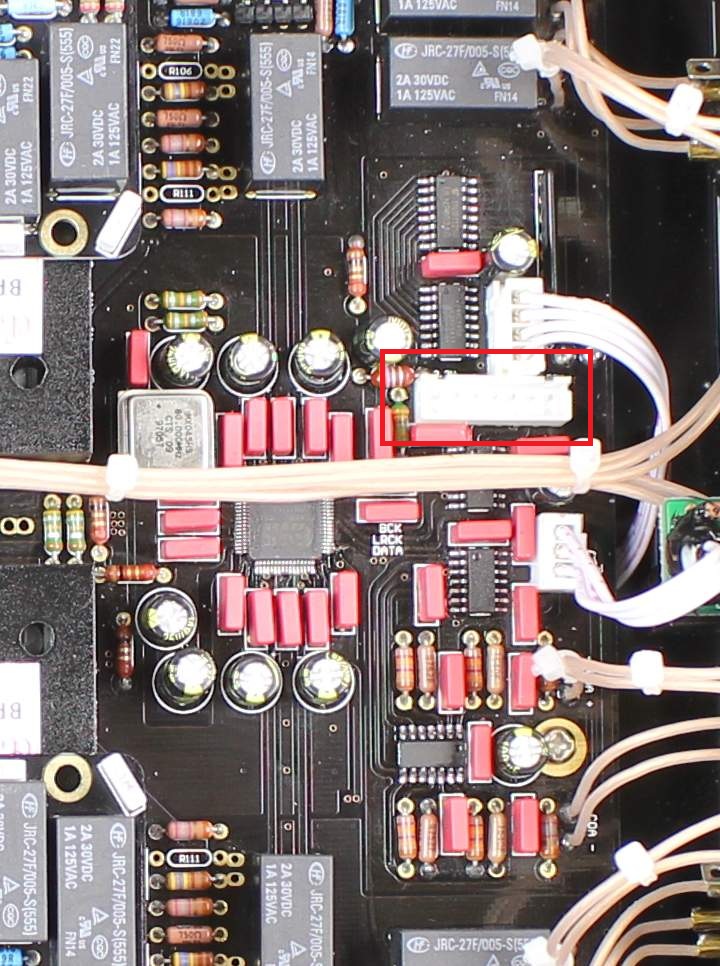
For the NFB-7(Had
i2S input):
( Order the Type 1 input kit, if you can't solder, please inform
”For NFB-7 avoid soldering" while place the order . We will build the +3.3V wire with the USB
connect wires, customer want to replace the USB connect wires for
avoid solder .)
1, Pull off the original I2S kit and its wires.
2, Assemble the HDMI input kit and push into the wires to the
I2S input on board socket.
3, Soldering the +3.3V wire in the +3.3V point, see the photo on
right. |
 |
|
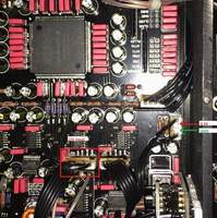
For replace the
USB32 or TE8802 built in the DAC
( Order the Type 2 input kit)
1, Take off the USB module and its wires.
2, Assemble the I2S kit and connect the wires correct. |
 |
|
HDMI model output kit modify guide
(The DIY always had the risk , we can't warranty any people can
finished the modify succeed and safe on the unit.) |
|
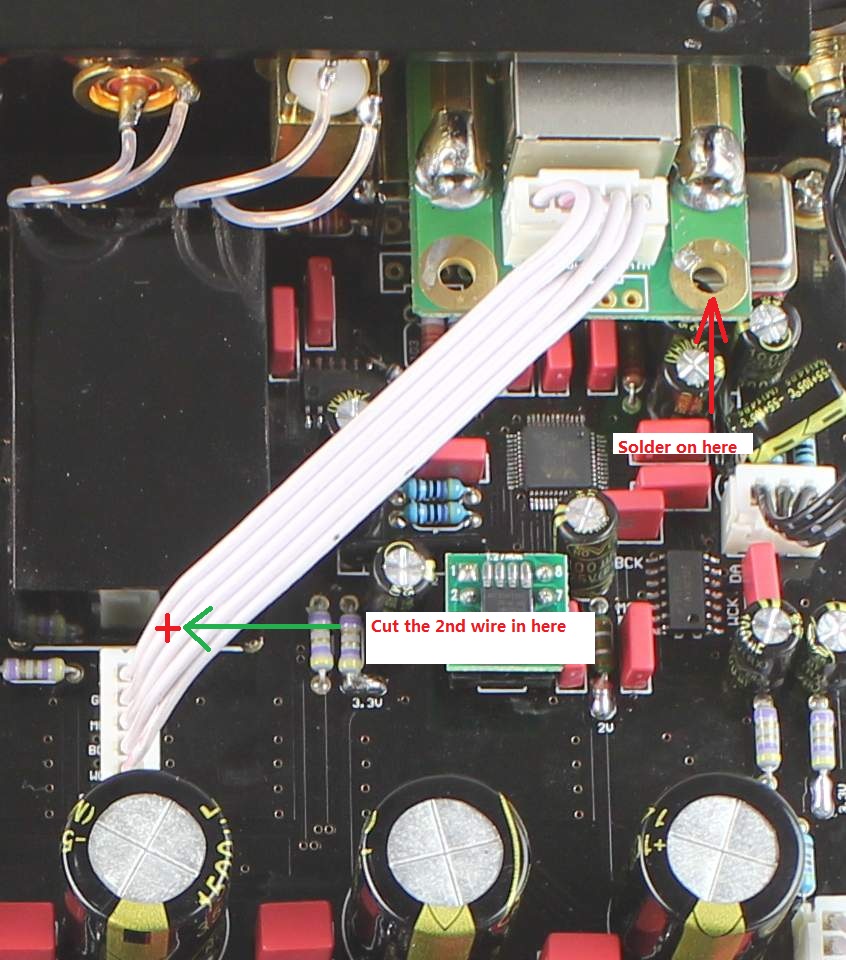
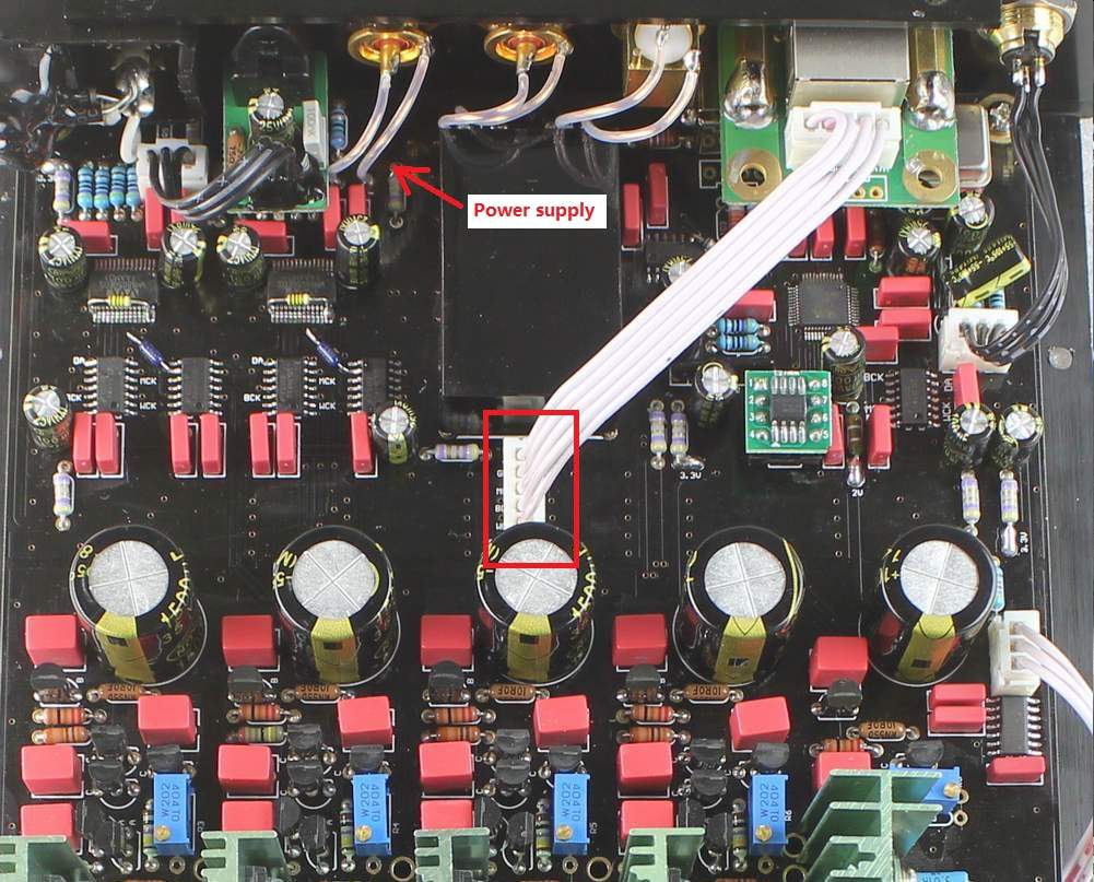
For DI-2014:
1, Pull off the original I2S kit and its wires.
2, Assemble the HDMI input kit and push into the wires to the
I2S input on board socket.
3, Soldering the +3.3V wire in the "power supply" point, see the photo on
right. |
 |