|
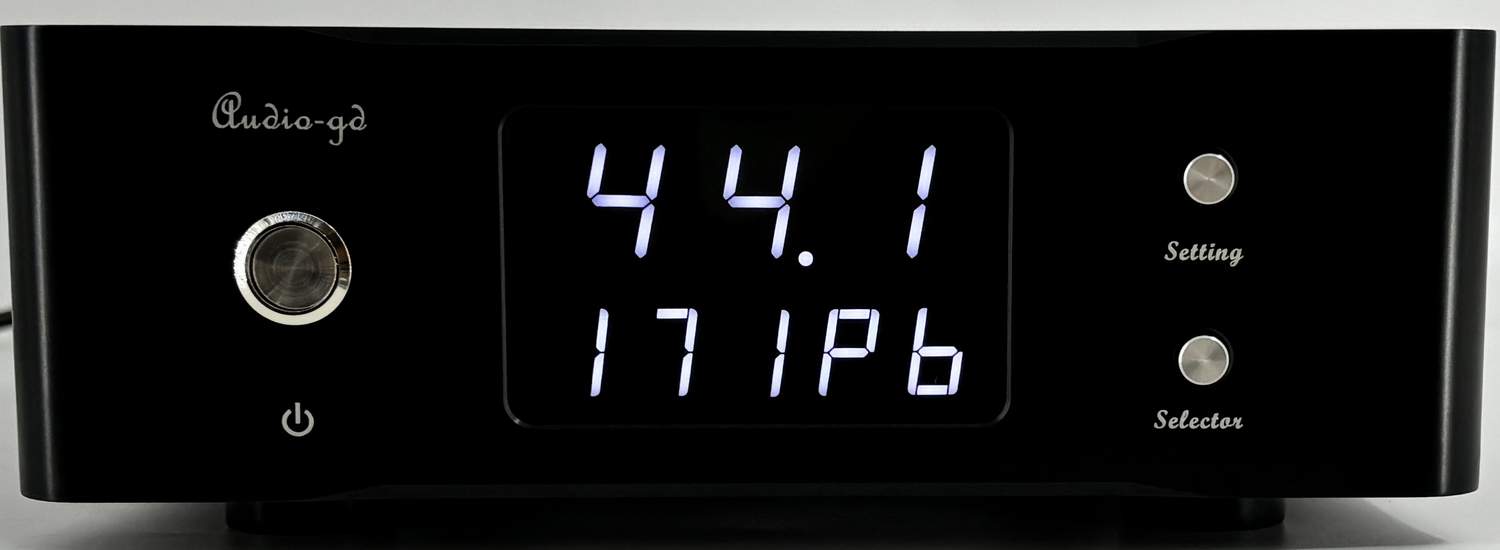
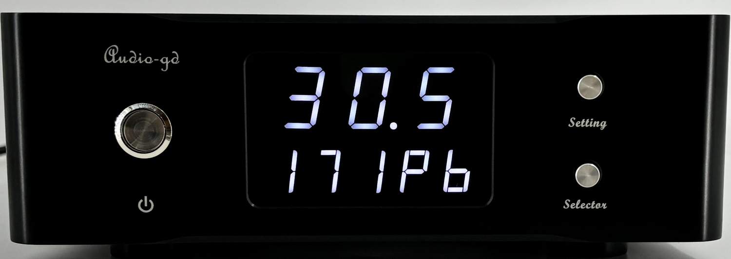
Button feature:
Leftmost button :
Power On/ Off .
"Setting" button :
Push once to go into
the setting menu, the display will be flashing. Settings can then be
modified.
"Selector" button :
Push to toggle
between the external and internal clock when the display not
flashing .
While the
display flashing, push this button to change and set the settings.
Display feature:
Digit on top:
Input signal
sampling rate indicator; 44.1, 48.0,88.2, 96.0, 176, 192, 352 and
384 are for the PCM formats, while 064, 128, 256 and 512 are for the DSD
formats.
When into the setting menu ,the
all digits on top show the unit inside temperature of centigrade .
Menu page 1
(Default display menu page 1):
Leftmost digit on bottom:
External/internal clock, "I" indicates the
internal clock is selected, "E" indicates the external clock
.When the clock connected, the
right bottom of this digit will light up a dot, that can go into the
setting menu to set the DI-24HE work with external clock. Otherwise, the
external clock cannot be selected.
If the
external clock lose power, or the cable has bad connect , even
though select the external clock, the "E" will become "I" (Switch
back in inside clock) automatically for avoid output noise.
2nd digit
on bottom:
Select 10MHz input clock
from 50 or 75 ohm port. "5" indicates the 50 ohm port, "7" indicates
the 75 ohm port .
Only both ports have connected
that can select, if only connected one port, no matter of the
selection but the Di-20HE will auto switch to the connected clock source.
3rd digit
on bottom:
Select output clock
from
external/internal clock, "I" indicates the
internal clock is selected, "E" indicates the external clock .When
the clock connected, the right bottom of this digit will light up a
dot, that can go into the setting menu to set the output from the
external clock.
4th
digit on bottom:
"P" (Parallel) means the signal will be processed internally by the
32 bit (PCM) or 64 bit (DSD) parallel
mode . "S" (Serial) means the signal will be processed by the serial
mode.
5th digit
on bottom:
"d" (dim ) means the display will automatically shut off after
around 10 seconds if no buttons are pushed. "b" (bright) means the
display will remain on.
Menu page 2
(When push "Setting" button
repeatedly ,when the 5th digit on bottom flashing, push "Setting"
button one more time that go into the menu page 2) :
Leftmost digit on bottom:
"n" (Non Swap) means the HDMI
outputs DSD with left and right channels following the Audio-gd
definition . "S" (Swap) means the DSD left and right channels
are inverted .
2nd digit
on bottom:
"1" means the PCM over HDMI i2s
output follows Audio-gd's definition . "2" mean the pins definition
follows other standard . (Read below for details ).
Rear plate
connectivity :
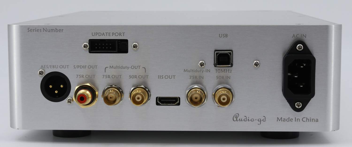
AES/EBU OUT :
AES/EBU output connector(3.3VPP @ 110
Ohm)。
S/PDIF OUT :
Coaxial output connector,
with built-in silver wire isolation transformer. (0.5VPP @ 75 Ohm).
Multiduty -OUT :
10MHz clock outputs (>9BDm at
50 ohm)
IIS OUT :
IIS signal over HDMI
output (3.3V LVDS @ 110 Ohm). It only can work with DACs using the
exact same pin definition. It can NOT work with mainstream
audio/video devices featuring HDMI inputs, and connecting the DI to
such devices could damage it, in which case the warranty will not
cover the repairs.
Multiduty IN :
75 Ohm external 10MHz clock
input (0.3VPP -3VPP @ 75 Ohm)
INPUT 10MHz :
50 Ohm external 10MHz clock
input (0.3VPP -3VPP @ 50 Ohm)
INPUT USB :
USB audio input(USB2.0/USB3.0)。
UPDATE PORT 10 pins port :
To connect the Altera Blaster and proceed
with an FPGA firmware update from Windows, using the Altera
programming software. These updates are meant for upgrading the
functionality and/or sound quality .
UPDATE PORT switch :
For updating the built-in Amanero
module's firmware through the USB input.
Must be
notice : If have not plan to update the Amanero firmware , must
can't touch this switch , otherwise the Amanero firmware be clean
and the product can't work !
Amanero firmware download link and guide :
http://audio-gd.com/Pro/dac/Amanero/AmaneroEN.htm
HDMI i2s output definition setting
(In the setting menu page 2):
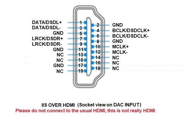
HDMI output mode 1:
The 1st display element indicates "n"
(Non swap) and the 2nd indicates "1"
(In the setting menu) : i2s out follows the Audio-gd
i2s definition.
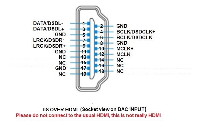
HDMI output mode 2:
The 1st display element indicates "n"
(Non swap) and the 2nd indicates "2"
(In the setting menu) :
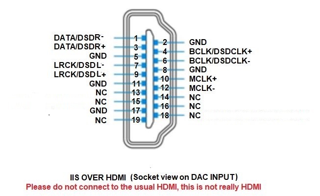
HDMI output mode 3:
The 1st display element indicates "S" (Swap) and the
2nd indicates "1"
(In the setting menu) :
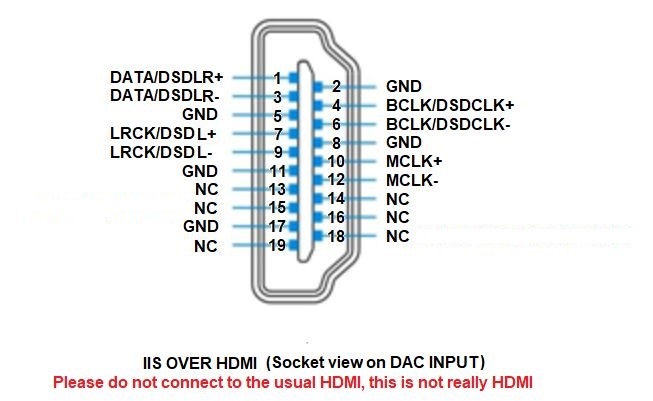
HDMI output mode 4:
The 1st display element indicates "S" (Swap) and the
2nd indicates "2"
(In the setting menu) :
|
