|
Please note:
The product even had burn in over 300 hours before shipping.
You can power on it with playing music if you are at home for
quickly finished burn in. If you don't want listen music during the
burn in term, shut down the amp.
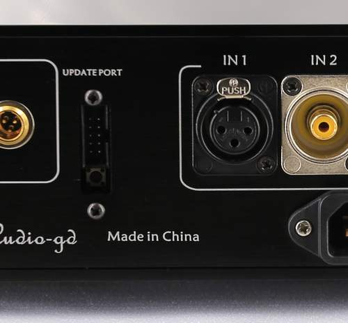
Please power off before connect or
disconnect the inputs and outputs .
Power on the product must had more
than the half minute after last power off .
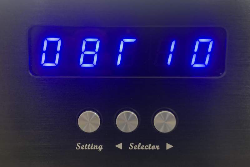
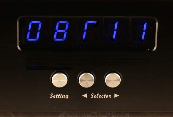
Working normal
state:
The Left 1st. display : Input channel flag , include 1,2,4,5,6 ( The
detail please read below text ).
The Left 2nd. display : Internal or External clock selection. While
connect the external clock, the dot of the bottom right corner has
light and mean the clock connection had succeed ( The detail please
read below text ).
The rest display : Input signal sampling , include
44.1,48.0,88.2,96.0,176,192,352,384 are mean the PCM sampling , and
064,128,256,512 are mean the DSD sampling.
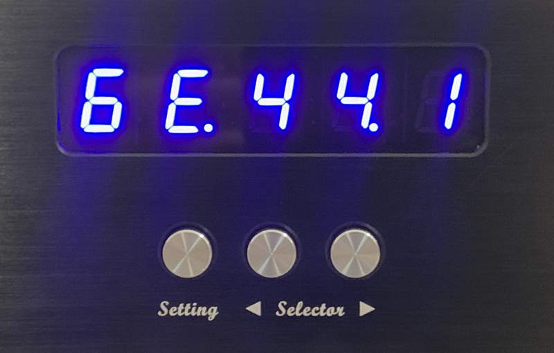
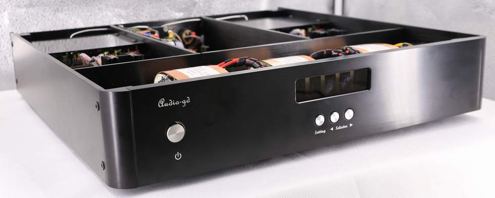
Buttons'
function:
Setting button :
Push the
"Setting" button one
time, the one digit display will blink for active the function
setting , push the right "Selector" button can change function . While
the display blink, push "Setting" again , the right next
one digit display
will blink , push the left "Selector" button the left next one digit
display will blink .
While the right 1st display blinking, push
the "Setting" one time , the menu will change to menu page 2.
Left Selector buttons:
While
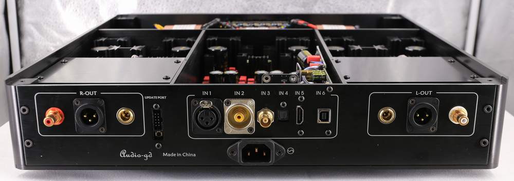
the display non blink, for select the input sources.
The 1st. of Left in the display show 1: AES/EBU digital input.
The 1st. of Left in the
display show 2: RCA coaxial digital input.
The 1st. of Left in the
display show 4: Optical digital input.
The 1st. of Left in the
display show 5: HDMI-IIS digital input.
The 1st. of Left in the
display show 6: USB digital input.
(IN3 is the 50 ohm
external clock input, setting through the below introduce )
The external clock input
impedance must be 50 ohm, and must match with same impedance
external clock generator and cable.
While the display blink,
for the setting digit move one left.
Right Selector buttons:
While
the display non blink, for select the input sources.
While the display blinking, for
setting the digital process functions.
Setting state:
Menu Page 1:
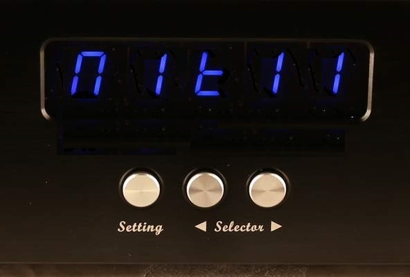
The Left 1st. display : OS (Oversampling)
O (OS) : For select oversampling.
n (NOS) : For select NOS mode.
The Left 2nd. display : Mode ( OS and NOS
modes)
While OS
setting on "O" mean the DAC working under oversampling
mode, loIr number OS modes sound became warmer
and smoother. Or depend on your sense .
0 : class
technology NOS mode.
2 : 2X oversampling.
4 : 4X oversampling .
8 : 8X oversampling.
While OS setting on "N" mean
the DAC working under NOS mode, it has one mode now, it is the full
new NOS configure design. We keep it has 1 to 3 because in future if
we update more NOS mode, users don't want replace the MCU.
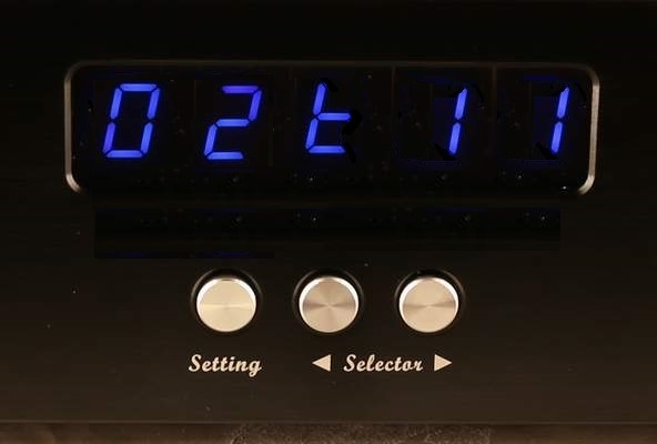
The Left 3rd. display : Simulate SAA7220 +TDA1541A sound)
t (TDA)
: Active simulate SAA7220 +TDA1541A, digital attenuation low to -55DB,
was -130DB. Bitwide low to 16bit , was 24 bit. While active this
function, I are advice setting to OS2 or OS4 mode. But infact, this
function can working with any setting mode.
r (R-2R) : Disable
simulate SAA7220 +TDA1541A .
The Left 4th. display : Internal
or External clock selection)
I (Internal) : Select the internal clocks.
E (External) : Select the external clock.
The selection only available
while the clock connection had succeed, otherwise the display show "Fail" if select
the external clock .
The Left 5th. display : reserved
Menu Page 2:
The Left 1st. display : Display
auto dark setting
A (Auto) : Active the display
auto dark, the display will become dark in around 10 seconds after
stop operate any buttons ,only leave a little LED light for figure
the unit power on. While user operate the buttons , the display
light auto .
n (Non auto) :Disable the display auto dark, the display light
always.
Setting
examples:
1,Set to most neutral sound mode
(8x oversampling, non TDA mode):
Push the "SETTING" button 1 times, the 1st. digital
of the 1st menu blinking, then push the "Right INPUT" set it to
"O" .
Then push the "SETTING" button 1 times, ,the 2nd. digital
blinking, push the "Right INPUT" set it to "8".
Then push
the "SETTING" button 1 times,the 3rd. digital blinking, push the "Right
INPUT" set it to "r".
2,Set to TDA1541
Simulate mode:
Push the "SETTING" button 1 times, the 1st. digital
of the 1st menu blinking, then push the "Right INPUT" set it to
"O" .
Then push the
"SETTING" button one times, ,the 2nd digital blinking, push the "Right
INPUT" set it to "0" or "2" or "4" (the number lower sound is more
warmer and smoother).
Then push
the "SETTING" button 1 times, the 3rd. digital blinking, push the "Right
INPUT" set it to "t" .
3,Set to NOS mode (New
configure NOS mode with simulate TDA mode for the one of the most warm
and smooth sounding):
Push the "SETTING" button 1 times, the 1st digital
of the 1st menu blinking, then push the "Right INPUT" set it to
"n" .
Then push the "SETTING" button 2 times ,the 3rd digital
blinking, push the "Right INPUT" set it to "t" .
HDMI
definitions : (Compatible with PS audio standard)
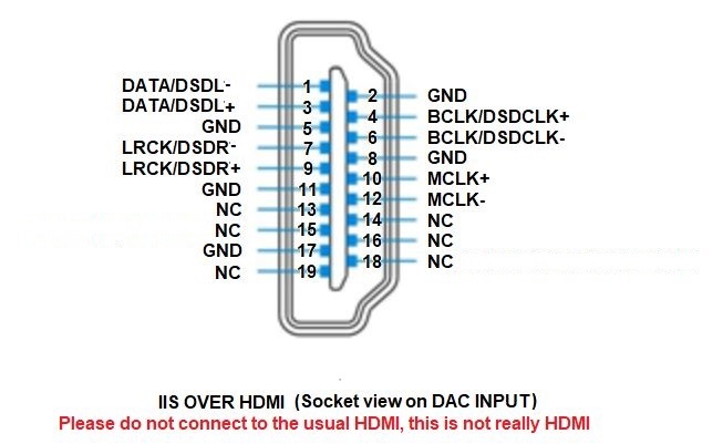
This product don't need the source MCLK signal but even the
source has MLCK output but has not effect .
|