|
Price:
( Exclude shipping cost)
Full upgrade version:
USD1680
Please send your address, name
to audio-gd@vip.163.com
get the quote.
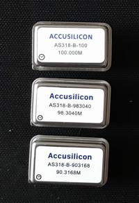
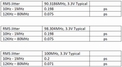
Accusilicon clocks:
Click to download the
driver of
Amanero
combo 384
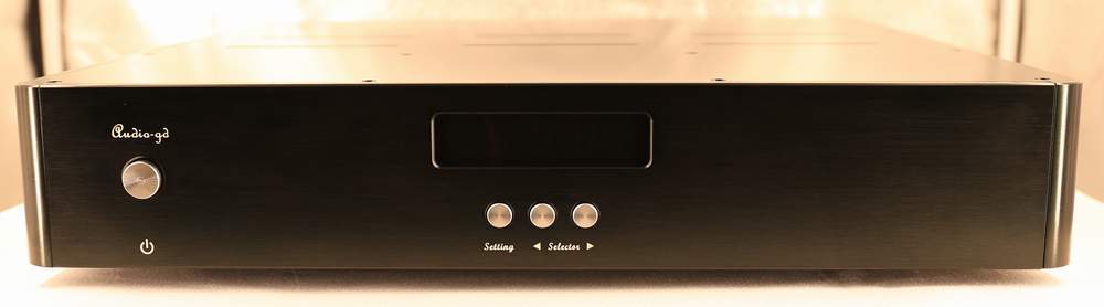
R-8 (2021 version) feature:
1, USB and HDMI apply the separate isolators
and isolate A PSUs for avoid the interrupt from computer
and HDMI sources. (New Feature)
2, USB apply the bidirectional isolator that
can transmit the IIS signal to the FPGA processor and receive the
clock signal from the FPGA processor, the USB interface without on
board data clocks, the signal transmit is much exact, the
sound quality get the much improve , similar to the last
generative R-8 combine with DI-20 (But not DI-20HE) level.
(New Feature)
3, HDMI input apply isolator for improve the
sound quality . (New Feature)
4, The FPGA process data in the parallel mode.
The IIS data is series transmit
mode, every data must need one clock cycle to process or transmit,
one frame data ( Include L and R data) must need 64 clock cycle to
process or transmit, so the data has effect by the 64 clock cycles.
But the parallel data process
and transmit mode only need one clock cycle can finish the one frame
data process
and transmit, that can avoid the effect of clock stability .
The IIS input (Include USB and HDMI-IIS) has recombine become dual
32bit parallel data once input , and the SPDIF input after decoder, has
recombine become dual 24bit parallel data, and the DSD input has
recombine become dual 64bit parallel data once input.
The parallel process and
transmit mode can improve the sound quality on the transparency and
detail but still analog.
5, Full new configuration clock
manage design built
in, improved on the clock timing.
6, DSD asynchronous clock technology
has apply that improves the sound quality obviously.
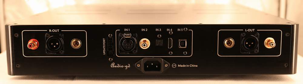
7, DOP support from SPDIF input .
What's the different to R-7 :
The
R-8 has kept all advantage technology of R-7 but applied SMD
technology to lower the cost and price. In sound quality, they are
quite close .
R 7 reviews : https://www.head-fi.org/threads/new-audio-gd-r2r-7-flagship-resistor-ladder-dac.853902/page-180
http://www.6moons.com/audioreviews2/audio-gd/1.html
Pros and cons of R-2R DAC :
Advantages:
1.R-2R will not convert the clock signal into the output
signal.
2. R-2R is not sensitive to jitter while Delta-Sigma D/A is
much more sensitive to jitter.
3. The output signal is much more precise compared to
Delta-Sigma D/A .
Weaknesses:
1.THD today is extremely good with Sigma Delta chips; R2R
ladders are good too but not as good.
2. Glitches and accuracy of the ladder resistors are very
difficult to avoid and require complex technology to resolve it. (We
have resolved through the firmware design)
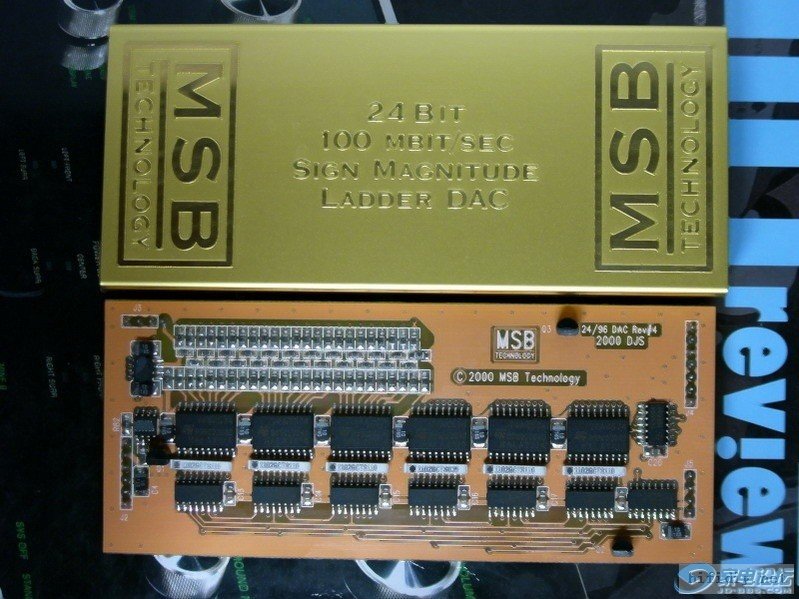
R-2R basic design in the market:
The
R-2R DAC is very popular nowadays and available from DIY kits and
all the way up to high-end products.
In the low range DIY market, the R-2R design is often
based on old technology designed a long time ago by MSB and only
includes basic R2R ladder design and do not include the wonderful
correction design of the original MSB technology. This design uses
data shift registers logic chips in series mode to convert the data
to an analog signal. The structural R2R technology issues cannot be
avoided, and performance is solely depending on the accuracy of the
ladder resistors.
In
the High-End market, the R2R design is much more complex and reaches
performance. A basic R2R ladder is simply not sufficient enough to
achieve good performance and sound quality! Some manufacturers are
using shift registers design. A less complex and lower performance
design based on traditional logic chips working in serial mode to
correct the ladder.
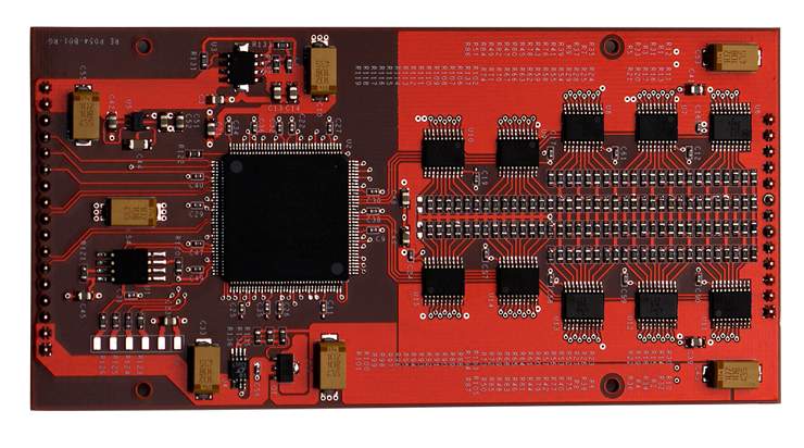
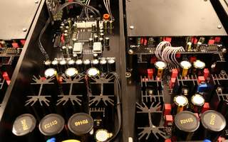
A far better design switches resistors in parallel mode. An
ultra-fast FPGA controls and corrects the R2R ladder. The parallel
design mode controls every bit respectively and therefore achieve
unprecedented performance. (In parallel mode only 1 clock cycle is
needed to output all data; serial design mode needs at minimum 8 up
to 24 clock cycles) The parallel design is much more complicated.
Once designed properly it can correct every bit of the ladder.
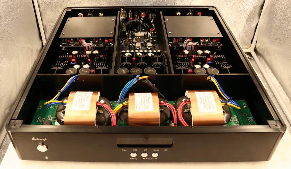
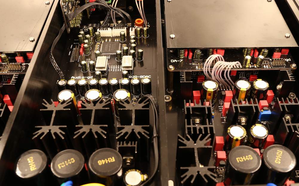
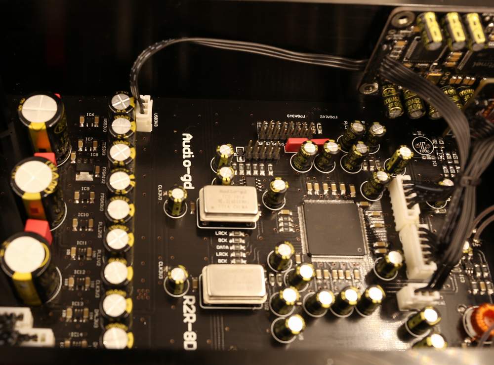
Photo below shows a design with such FPGA, can correct the
unavoidable imperfections of the R2R ladder caused by tolerance of
resistors, glitches to achieve best performance.
Accuracy of the ladder resistors
(tolerance):
Many people believe the tolerance of the
resistors in the ladder is most important to reach best performance.
Nowadays 24 bit resolution is standard. What tolerance is needed to
achieve 24 bit resolution?
When we look at 16 bit the tolerance of 1/66536, 0.1% (1/1000) is
far not enough, even a tolerance of 0.01% (1/10000), the best
tolerance available in the world today, still cannot handle 16 bit
request correctly; we are not even calculating 24 bit here!
The tolerance of the resistor will never solve Imperfections of a
ladder. This would require resistors with a tolerance of 0.00001%
and can handle 24 bit resolution. This is only in theory because the
discreteness of the switch logic chips have already too much
internal impedance and will destroy the impossible tolerance of a
resistor.
The solution is to correct the ladder and not only depend on the
tolerance of resistors. ItĪ”s a combination of both: Ultra-low
tolerance resistors controlled by a correction technology using very
high speed FPGA are applicable in in our design.

Ī@
Importunacy of the FPGA/CPLD:
FPGA
stands for Programmable Array Logic.
Nowadays the FPGA is applied in a lot high end grade
DACs; like the popular ROCKNA WAVEDREAM DAC.
We have
applied the FPGA in our DAC products since 2008.
R-7 has built
in 1 pc FPGA and 5 pc CPLD programmable chipsets to separate the different
configured circuits for avoid interrupt.
The internal hardware design is fully controlled by
complex software. A huge advantage is the fact the software in the
FPGA can easily be upgraded offering new features or improve the
performance. Such design is much flexible and future proof!
Ī@
FPGA/CPLD tasks :
1. The FPGA
high performance SPDIF interface, replacing
traditional SPDIF interface chips like DIR9001, WM8805 or AK411X wich
are lower in performance in comparison to FPGA.
2. Full re-clocking process with FIFO design applicable
on all inputs. This way the output data keeps fully synchronized
with the clock signal to reject any jitter.
3. Built in 2X, 4X and 8X oversampling and digital
filters and on top of this 4 different true NOS (only analog 6dB
filtering) modes. To completely configure it to your liking!
4. Built in the
especial design to simulate the TDA1541A + SAA7220 sound flavor.

Fully discrete output stages
The
signal last stage is the analog output stages, which can greatly
effect the whole DAC sound quality.
After d/a conversion by the R2R D/A modules the analogue
signal is transported by fully discrete matched-transistor output
stages.
The high speed special ACSS output stages are non-feedback and current driven design.
Almost all other designs need to convert the signal
multiple times from and to current or voltage, resulting in less
detail and less defined sound stage .
The output buffers are single ended FET. Two stages in
parallel to reach very low output impedance. All output stages are
in pure class A design without any (negative) feedback to achieve
purest and a real live sound reproduction.
The 4 OPA opampŻŠs are functioning as DC servo, this way no
coupling-capacitors are needed and DC output is automatically
biased! Resulting in a perfectly neutral sound.
There are no relays or other switches in the signal path
after D/A modules to allow the best and purest sound quality.
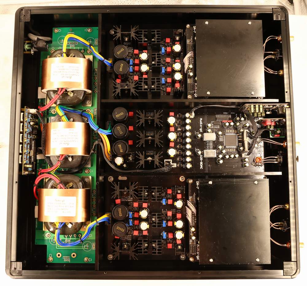
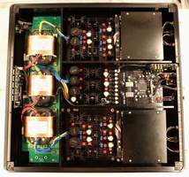
Heavy power supplies design:
The
DAC has 3 high quality low noise, low flux leakage, R-cores
transformers.
In total 130W power to supply all digital parts and the
left and right analog boards.
The digital parts DC power is distributed by 13 ultra
high speed low noise PSUs, they are group became the double stages
PSUs .
The analog parts DC power is distributed by 10 groups
PSUs group became double stages PSUs .All are pure class A low noise
regulated power.
This results in ultra-high speed and ultra-low noise
performance. Clean and independent power for all different parts to
achieve highest quality.
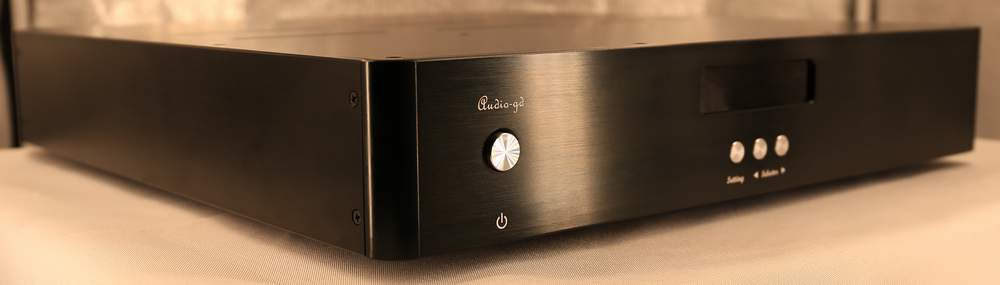
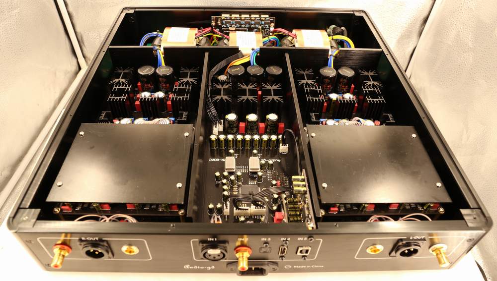
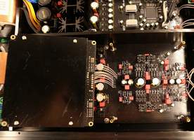
Finishing touch:
The R8 has completely separated power supplies .Digital, left and
right analog channel have their own dedicated transformer. All
boards and transformer compartment are separated by 5mm thick
aluminum plates for high isolation degree.
It improves the signal-to-noise ratio, isolate the
harmonic interference and reduce noise, which will make the sonic
background cleaner and blacker.
The Left and Right analog parts are placed symmetric
beside the digital board to keep the wires and distance identical to
ensure equal output performance on both channels .
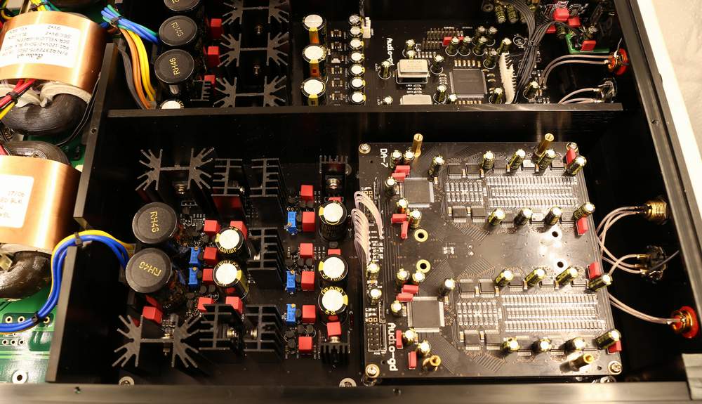
The R2R D/A modules are assembled between two aluminum
boards to avoid any RF interferences.
|